I have a DCC900 r/w board that I have to calibrate to a new 166 mA DCC head.
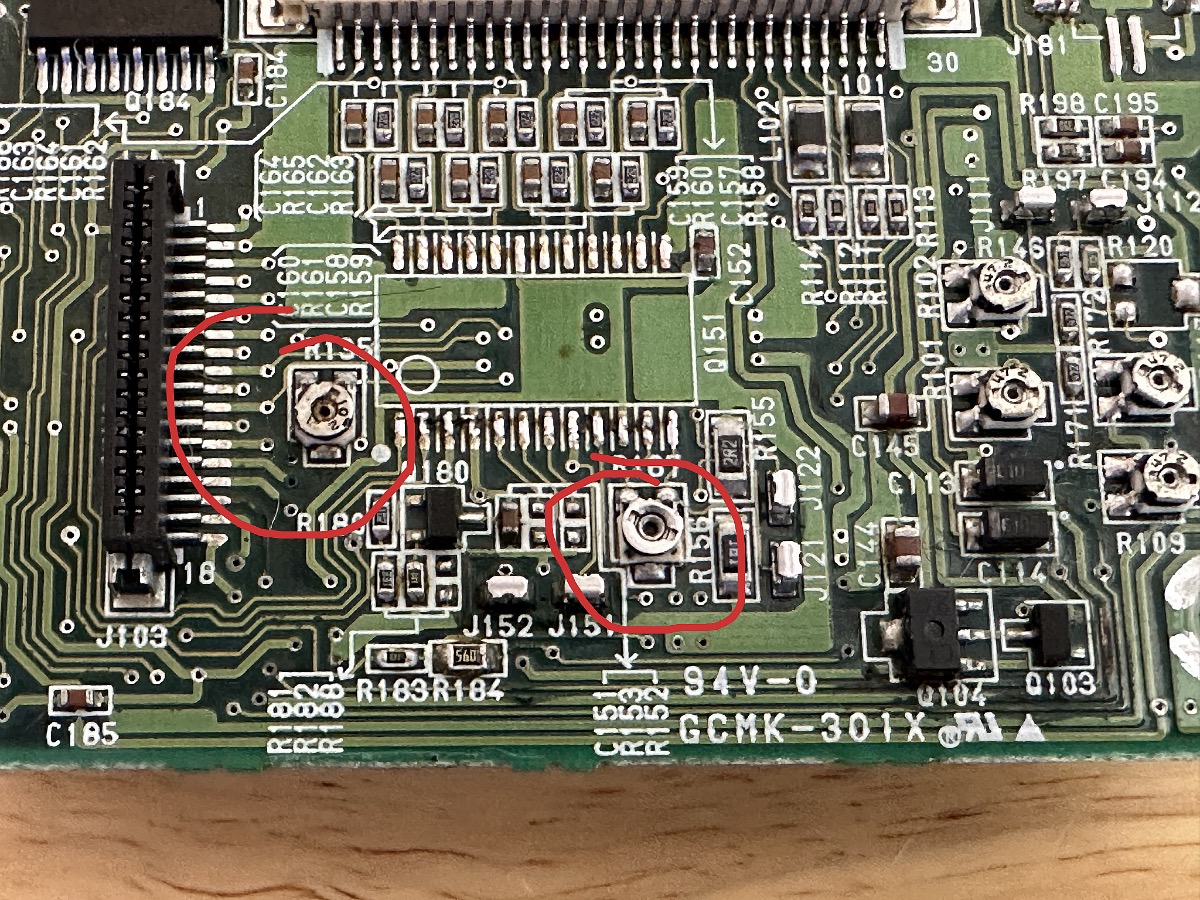
Normally, adjusting rec monitor adjust outputs somewhere between 1,4 and 1,6 using a multimeter and measuring the two contacts J151 and J152.
This board shows values between 0,9 and 1,0 mV, which is way too low: recording is a mess.
Its not clear from the schematic exactly how the 166 mA write current required at the head relates to the voltage measured across R151 but from your description it seems 1.6 mV indicates 160 mA of write current so obviously 1.0 mV is too low. Normally I would say check that the value of R151 is actually 12 ohms as if this value has decreased under constant current conditions it would lead to a lower voltage reading; but you report that recording is still a mess at any position of R167. From the schematic if Q180 was faulty (e.g shorted or switching on too hard) it would rob current from the current amp inside Q151 (write amp IC). Similarly if Q185 pin 13 was stuck high the transistor would remain on and not switch as it is supposed to do. Also check the values of R180- to R182 as these would have an effect on Q180 switching thresholds. In fact the whole circuit involving Q181 - Q185 is under suspicion as it performs the function of “auxiliary current shift” and could be affecting your reading. Check each of the flip flops and counters for correct operation ( I know, easier said than done). Also check R156 and R155 as they may be preventing you turning up the wick on the write amp properly if they have gone short or changed value. Lastly what happens if you unplug J181? It is marked MR head ( I don’t know what that does) but it has a NTC thermistor in it which could be affecting voltage at J151.
Me again. I should of course have first advised you to double check you have a good strong 5 V supply to your read/write board (always check there’s gas in the car). If it’s sagging below this it will be the cause of your trouble. This is the board with the notorious SMT electrolytics and they can turn in to low value resistors if/when they leak. If your voltage is low, check the voltage regulators on the main board to see if they are hot by touching them. Most likely one of your caps has gone short if this is the case.
Are you using the new read write board? Otherwise the comments earlier are really good. It means there is a different problem. Could even be TDA related.