Hi everyone!
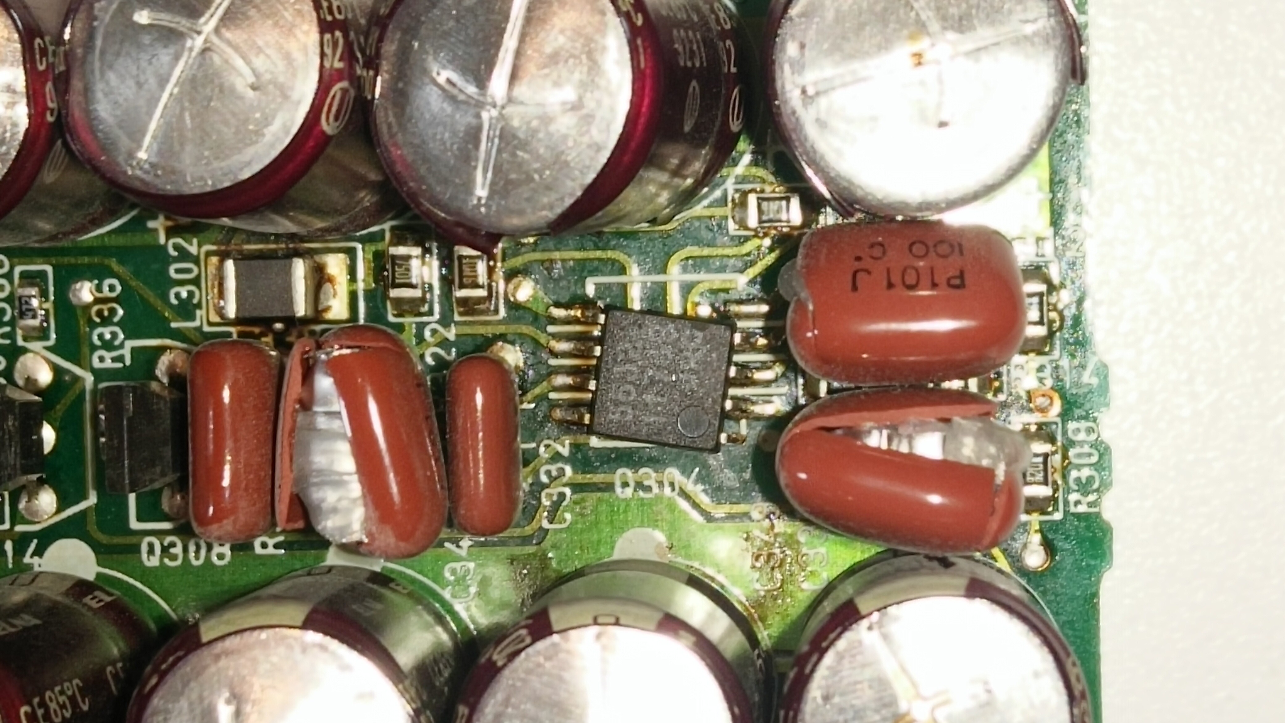
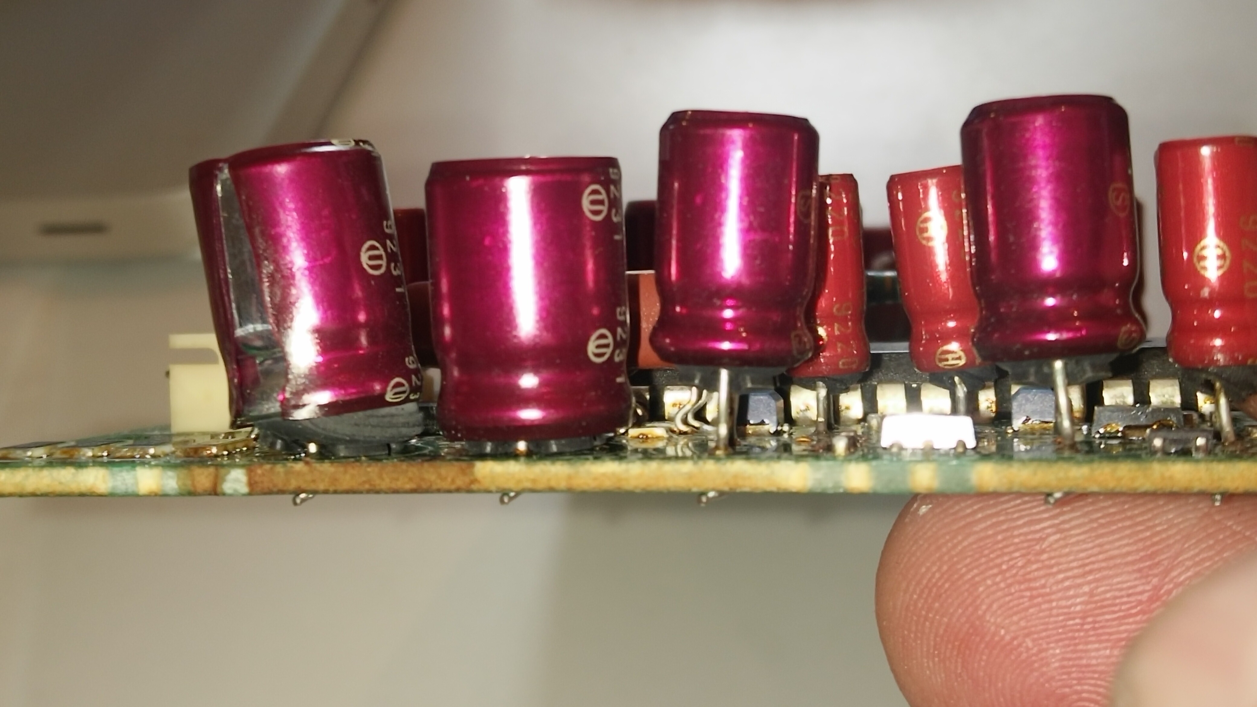
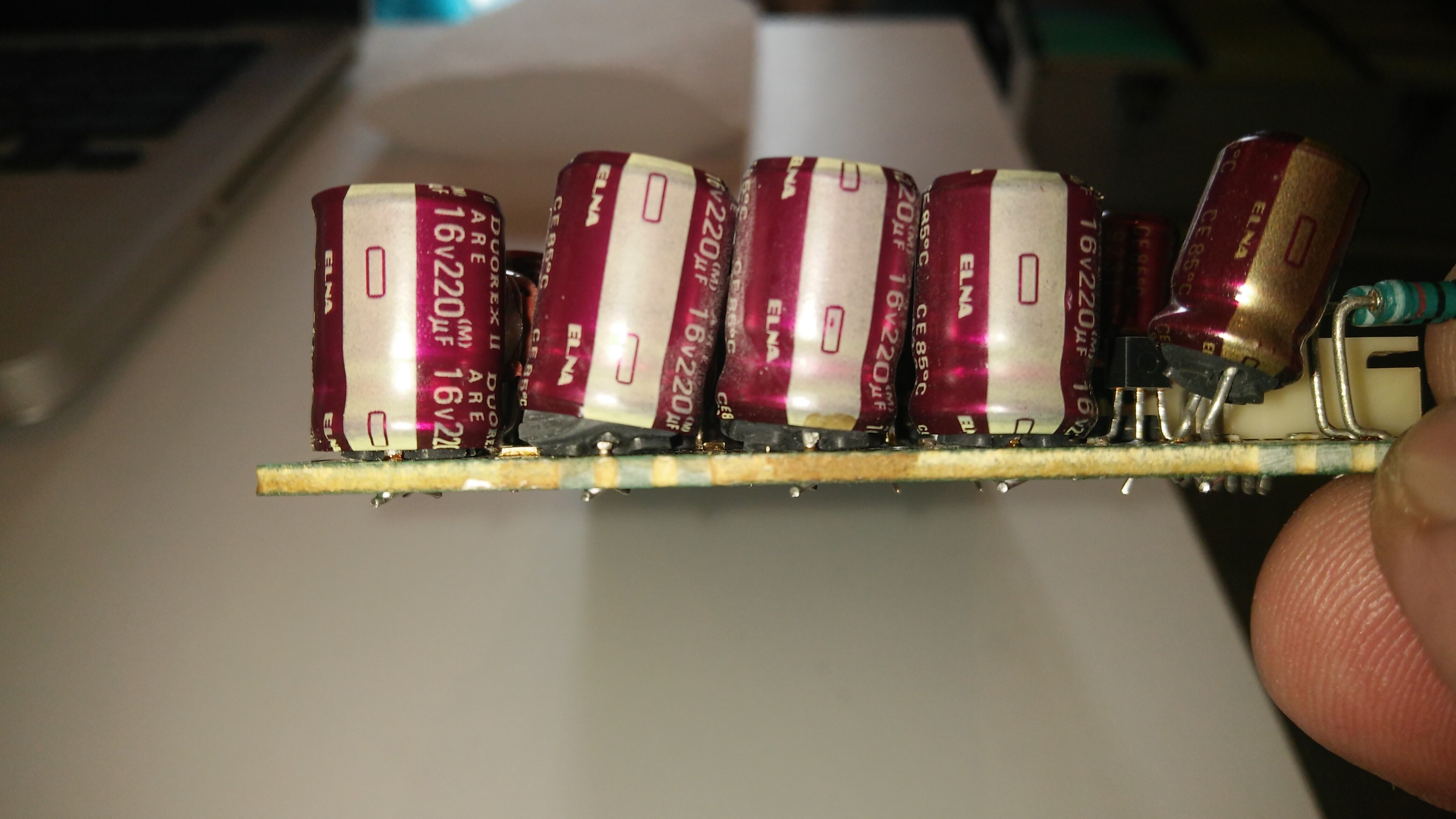
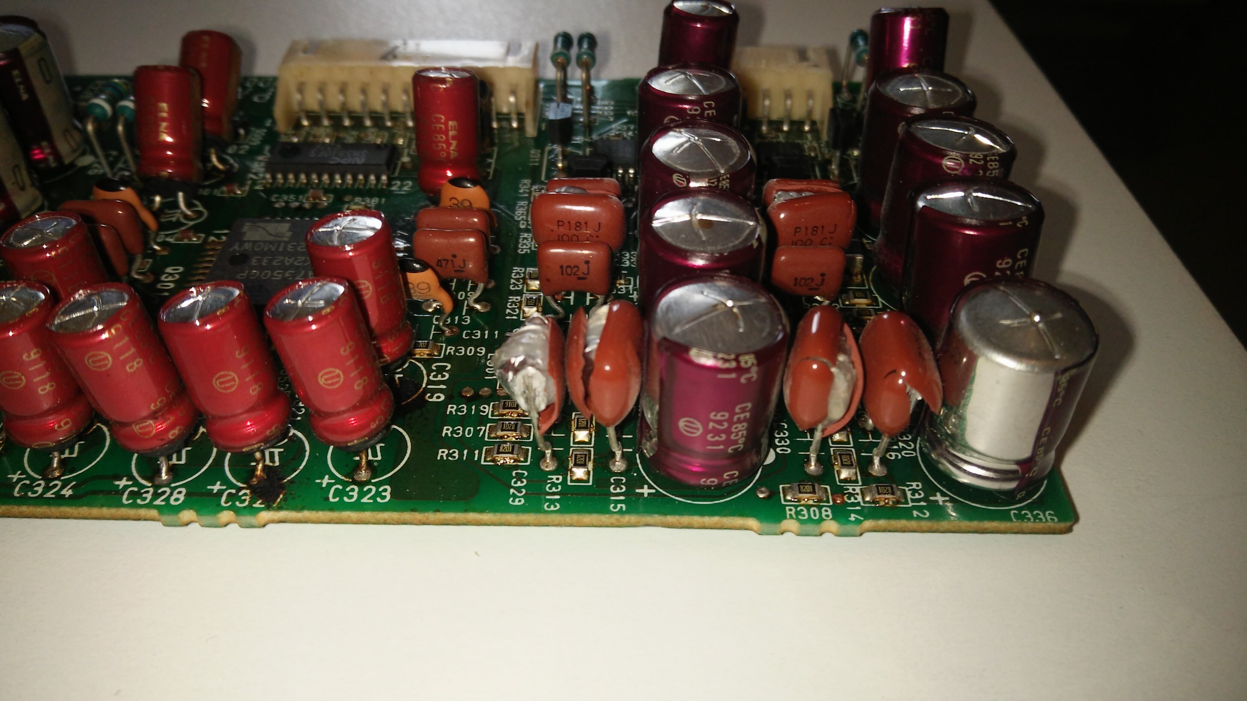
Recently bought a DCC 900 and started to replace the SMD capacitors. I’ve done the read/write board and when I removed the other board noticed something wrong with the AD/DA board, meaning some film capacitors exploded and most of the electrolytics not looking right at all.
Also, one of the 5532 chips is soldered quite weird, see the photos.
Initially was no sound, after the read/write board recap the right channel with sound the left no sound.
My question is, what could cause the issues with those capacitors on the AD/DA board? Wrong voltages, overheating?
That chip could have been soldered like this from factory?
The magic smoke escaped, did it at least smell good? Did the 5532 really came like this and you did not move it accidentally with hot air or something? I would at least purchase a new one and solder it in correctly. Your read- and write-amplifiers may be fried, please wait for advice from @drdcc and @Jac before doing anything with it except maybe desoldering the exploded caps.
I bought it like this , didn’t happen to me. I didn’t touch the board, all the photos were taken after I removed it. It doesn’t look like someone worked before on it. I will open my other DCC a Marantz DD 82 who is identical and I will compare the 2 boards. Of course I won’t do anything till I have a clue what could cause that. No point to replace the capacitors before that.
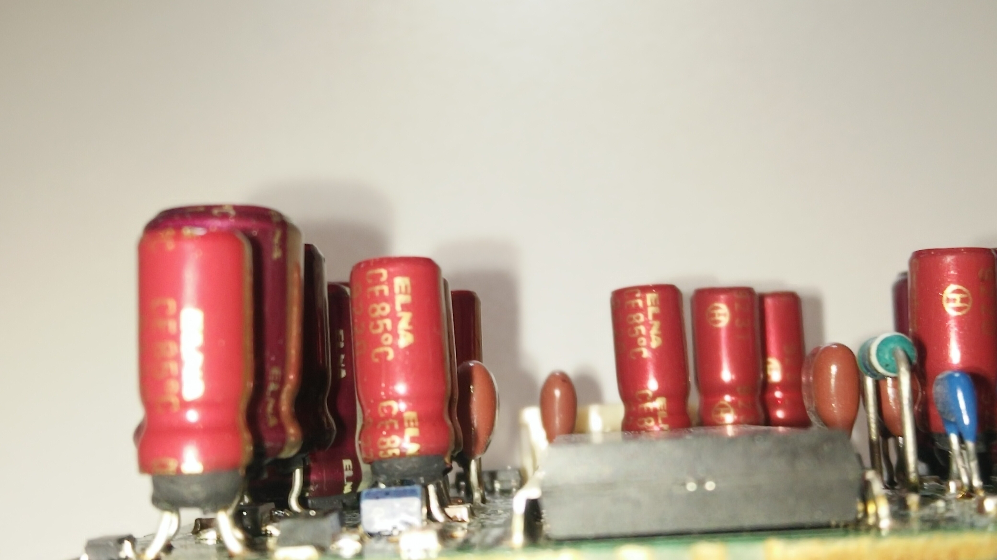
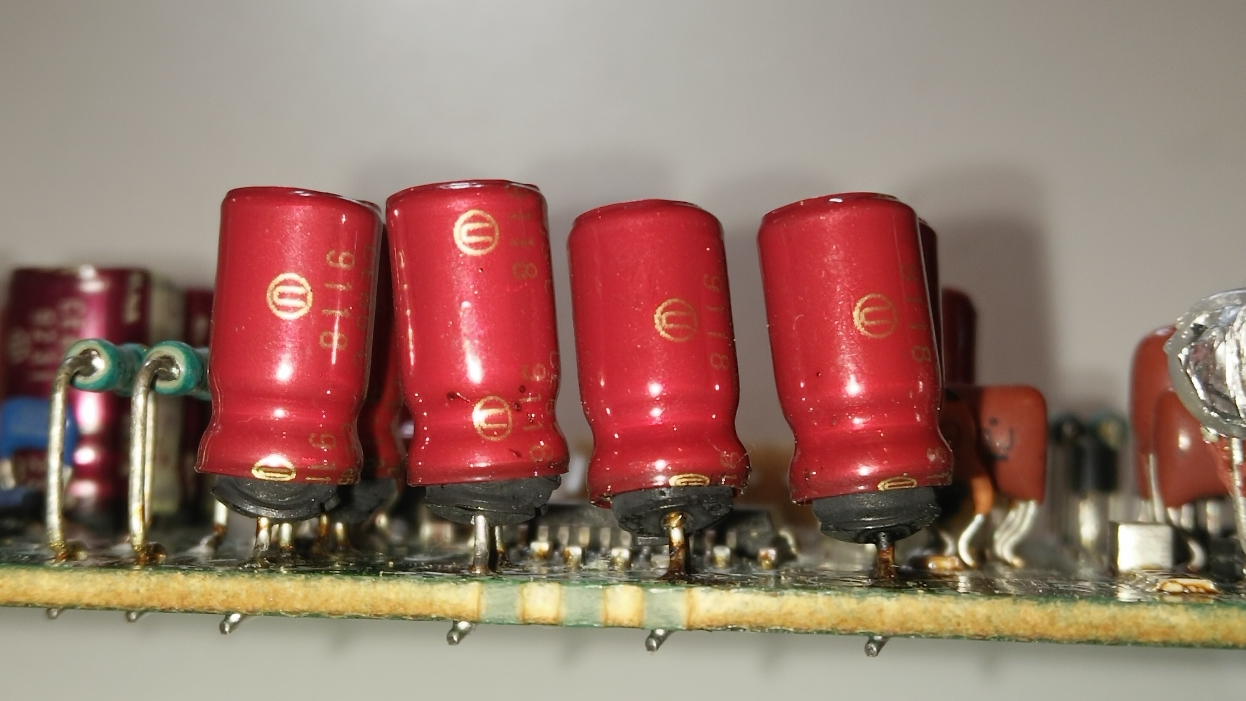
Looks like a bad accident happened to this one. Almost all capacitors have exploded.
I would say this board was on a higher voltage than it was supposed to be, for a long time (at least several minutes). Either that, or the voltage was negative for some reason.
That chip isn’t supposed to be soldered that way of course. Maybe it exploded from the bottom and launched itself from the board or something.
I would say the chance that this can be successfully repaired is going to be slim. There’s a good chance that besides the capacitors, there are other parts that didn’t make it through the ordeal, whatever it was.
Hi, @Jac is right. That board has been exposed to something very strange. The good news? It is a very easy to replace board and we have plenty of them in stock. No need for recapping. Just a straight swap.
Parts available for Patrons of the dcc museum. You can contact us at [email protected]
You might also want to check the larger motherboard for damage first.
Hi Ralf,
Thank you very much for the good news, I will contact you right away via email. Meantime i’ve started to investigate the voltage rails for this board and it looks like the +12V rail measures only 4.9V, so need to check more why. Also, I’ve inspected the main board for any damages, nothing visible yet. My bet is this board was originally on another player, probably one with 110V main and someone replaced it in this player.
Since the mechanism works and already I have analog signal in one channel after recapping the R/W board , I think it might be a chance if I replace completely the AD/DA board to make it work. I will post any updates soon. Keep in touch and thank you all!
Measured again voltages for the AD/DA board and now looks right.
On J311 main board connector is +5V,-12V,+12V.
On J313 manin board connector the reset Pin is 5V , 44k FS pin -12V, 48k FS pin -12V.
Is this right for the J313? According to the schematics those voltages should be there, but wanted to confirm, still learning new things.
Thank you.
Update:
A new board arrived , thanks to Ralf @drdcc.
Installed it today, capacitors replaced in R/W board and the digital board.
Plays fine a tape but the bad news, it doesn’t record.
Tested both with analog and digital input, looks like it records but it doesn’t.
I’m thinking of the R/W board but where should I start looking?
Any advice much appreciated.
Thank you.
It is clearly visible that the non-polar capacitors have blown too. I recon there has been a very high voltage being put on the board. My bet is that all parts on the board are destroyed, and all semiconductors (internally) too.
Don’t bother repairing it, it’s a waist of time. If any parts are still working, they might not be in the near future. Just ask the museum for a swap board.
Regards, Henrie
Update: It’s only now I see the thread continued, so I’m a bit late. Sorry about that
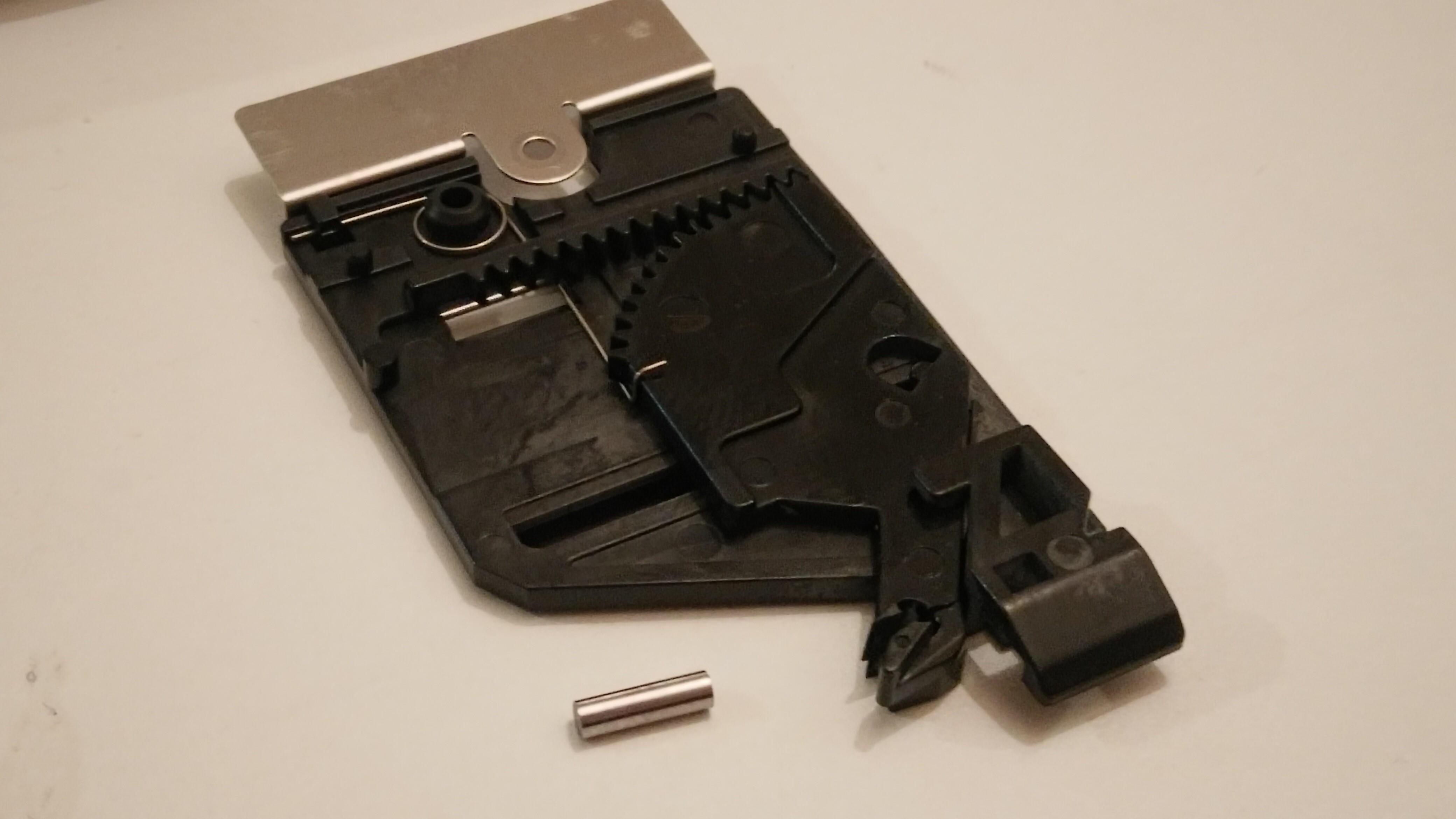
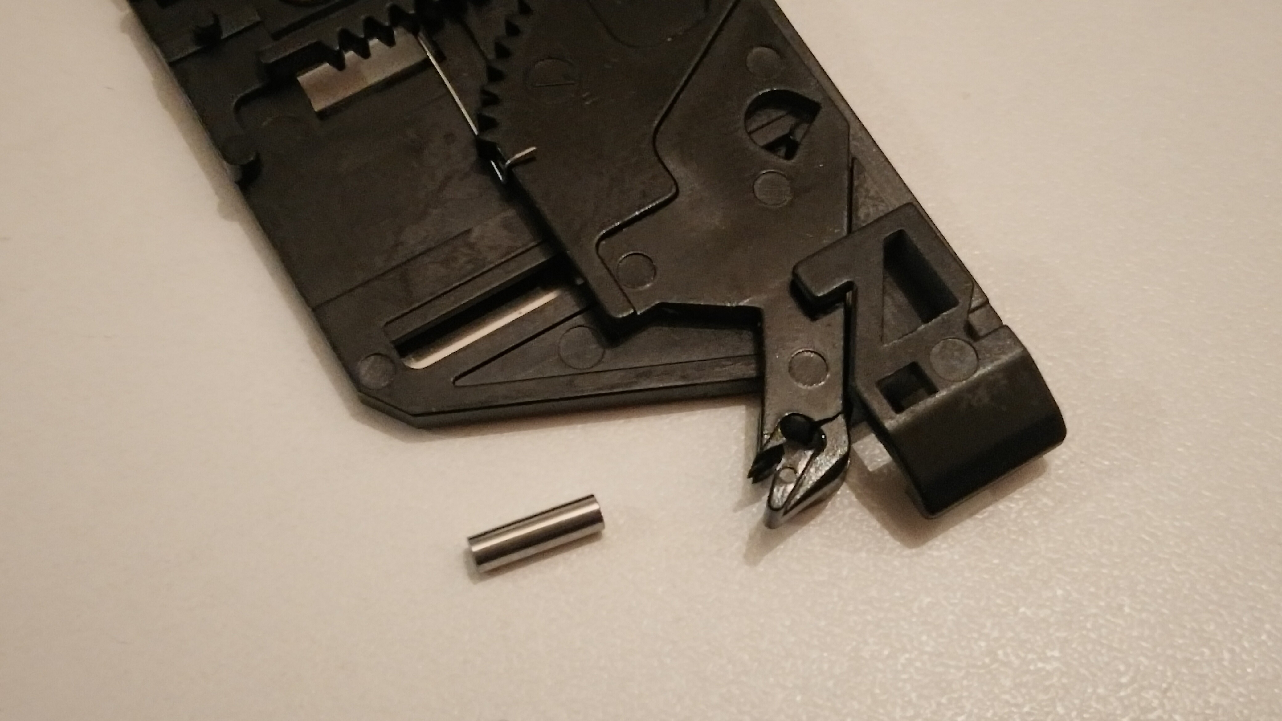
Unfortunately, no because when I tried another tape it won’t load it and discovered the plastic part with the metal pin which is opening the tape protection broken.
Can it be repaired? Which glue to use?
Same happened to me, but I couldn’t find the pin no more… I even opened the unit, flippd it, nothing. Tried a piece of a nail, it was good length but the plastic area broke for good (where the original pin was). No glue can hold it well… So far I am using ducktape to keep the metal slider open. This until I will buy the spare from @drdcc (hopefuly soon).