A Philips DCC 600 that is for sale has a dark, irregularly lit display. I have read that this can be caused by a defective power supply to the display (possibly a defective capacitor). If not, is it known if the display itself is the problem on these devices?
Whenever a vacuum fluorescent display (VFD) is weak, it’s usually caused by the negative high-voltage power supply. I don’t remember off-hand what the voltage is in the DCC600 (check the service manual) but it’s usually something like -70V. And yes, the defect is usually caused by a leaky capacitor.
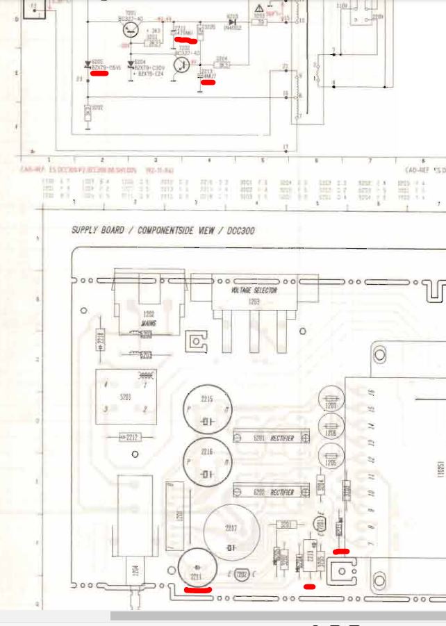
Check and replace these parts-the zener is responsible for even brightness througout the tube (forcing filament supply middle point within cathode voltage range) and the caps are most likely worn if the dim is even. When the zener fails, it may take out other parts.
The DCC 600 arrived yesterday. Unfortunately the display is not only dark but there is no display at all. And the rest of the machine doesn’t work either. I will check the power board and hope that my electronic skills will be good enough to find and solve the problem.
I measured the outputs of the circuit board.
I measured the following values:
PIN 8: -0,46 V (instead of 30,7V)
PIN 7: 13,6 V (instead of 15,2 V)
PIN 6: -26,8 V (instead of -17 V)
PIN 3: 14,6 V (instead of 7,7 V)
So here is the answer, why the display is off. I measured already the 39 Ohm Resistor and the capacitor 2211. The resistor has 39 Ohm and the capacitor has 580 MU instead of 470 MU.
however, I do not yet know how to test zener-diodes and transistors.
Thanks to André I could repair my DCC 600 today! He gave me a spare unit (the drive was destroyed) from which I was able to use the power supply. (I bought the DCC 600 as defective two weeks ago for 89 EUR in Poland).
The device is in very good external condition and now, with working power supply sounds great.
And the biggest surprise is that the DCC 600 can cope with difficult DCCs that my DCC 730 couldn’t record (when recording with the DCC 730, there were the well-known dropouts because the skin pad is getting on in years).
I am very happy!
Just FYI – capacitors are measured in microfarads (μF), not "MU"s. The Greek letter μ indicates “micro” in this case – although since that letter is hard to type unless you actually have a Greek keyboard, a lowercase “u” is also acceptable; i.e. “470uF”.
(You will also see smaller capacitors given in pF, or picofarads. Rarely, you might see a capacitor written in “nF”, or nanofarads – i.e. 1nF rather than 1000pF or 0.001uF – but it’s not common, at least not in my experience. Really old radio schematics might also list them as μμF – micro-microfarads – rather than pF, but that’s pretty obsolete nomenclature and no one’s used that since the 1950s or so. )
Zener diodes can be tested by measuring the voltage across them with a voltmeter, with the red (positive) probe on the cathode side and the black (negative) probe on the anode. The voltage across it should be close to what it is rated for. To get the most accurate result, it should be removed from the board and tested out of the circuit, if possible. This page has a good technique:
There’s also a very basic technique for testing transistors on that same site:
Although if you’re serious about electronics work, you might want to invest in a proper transistor tester. They’re not all that expensive, at least not here in the USA. (I admit I don’t know anything about the pricing for such things in Poland, though. )
Thank you for your post, the information is very helpful for me.
I think a transistor tester like the one you mentioned would really simplify testing.
I found the faulty zener diode (and a shop near me that also had this diode in stock).
I had used the notation “MU” because it was used in the power supply schematic. In fact, I had also assumed that the unit “µ” was meant.
Tomorrow I’ll start repairing the power supply unit, I’m curious to see if it works.
Thanks again!
Now that’s very strange… now that I look at the schematic image didyman posted, it does say “MU” for the capacitance notation, doesn’t it! That’s a new one on me; I don’t think I’ve ever seen a schematic where the capacitors were rated as “470MU” before…
(Though come to think of it, I have seen a couple of old schematics which said “mF” and “mmF” for microfarad and micro-microfarad; but again, those were really old radio schematics with obsolete notations that I don’t think have been used since the 1950s or early '60s…)
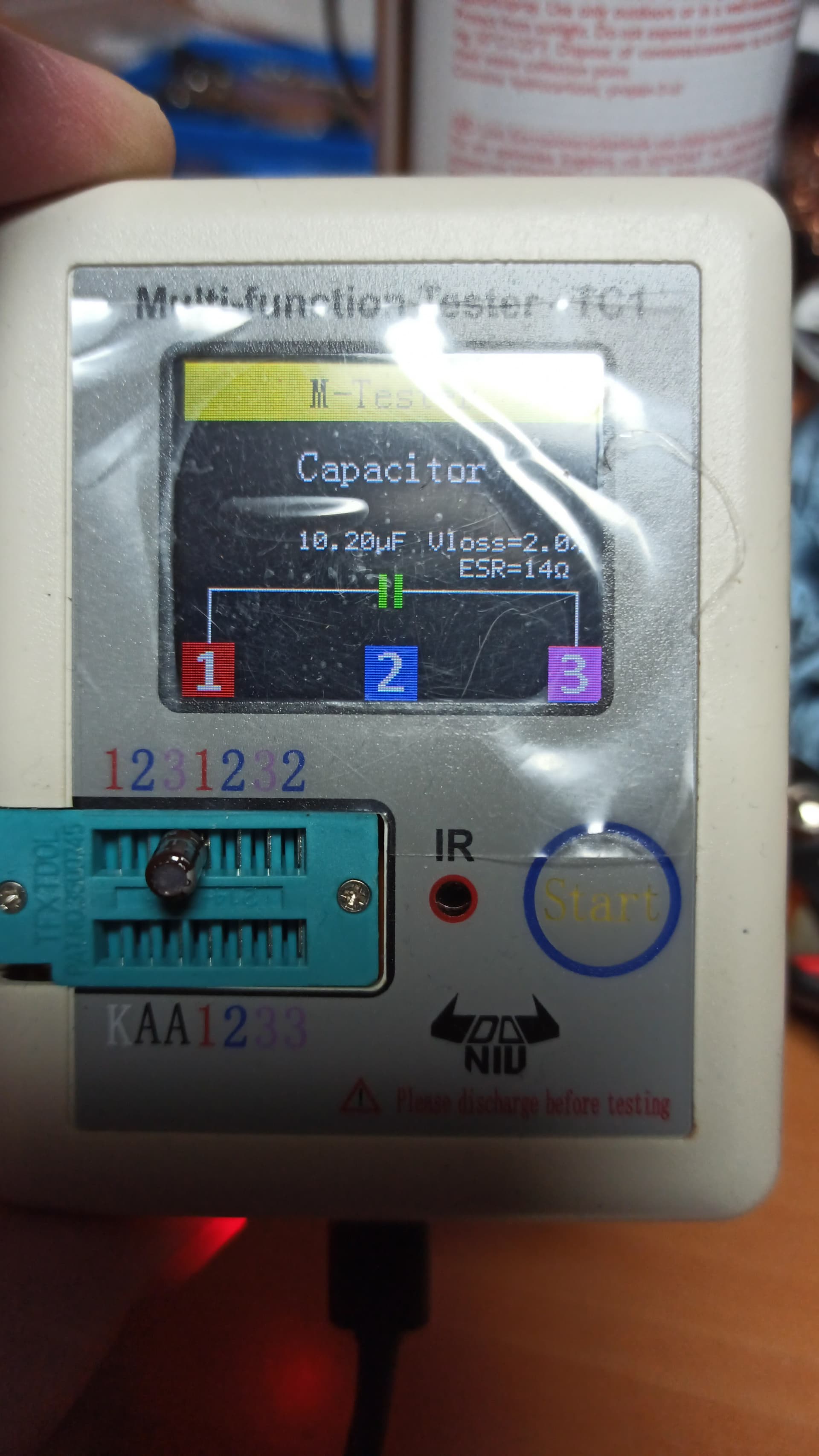
Transistor testers are extremely useful devices to have on your bench if you’re going to do component-level repair work. There are even some really nice “multi-function” testers out there nowadays that not only test transistors, but other components like diodes, capacitors, and inductors as well. Like this one: https://www.amazon.com/Transistor-DROK-Capacitor-Capacitance-Automatic/dp/B01MS1FOYM/
Not sure if this exact model is available to you in Poland or not, but Amazon (US) has about a dozen different vendors selling various versions of this, so it wouldn’t surprise me if something similar is available from a vendor there in Europe.
The power supply is repaired, tested on the Philips DCC 600 and everything works!
It was a defective transistor, the 7201 (Type: BC327-40) and a defective zener diode, the 6204 (type: BZX79-C24).
It doesn’t reach the -30.7 V specified in the circuit diagram between PIN 8 and ground on the plug (measured only -24.4 V), but the deck apparently works with it.
Thanks again for all the tips!
And, I will order a multifunction tester!
However, if not already done, I would replace the 470uF capacitor ASAP since it was most likely the reason for the transistor and zener failing at an earlier stage. Its probably dried out now as well so I wouldn’t trust measurements except for ESR.
And the voltage seems fine. I only measured about -24,4 volts on a second working power supply between PIN 8 and ground on the plug (instead of the - 30,7 V in the circuit diagram).