I am trying to fix DCC900 which I bought as defective. Clearly someone tried to fix it before me and apparently gave up.
I’ve replaced all SMD caps on the PW03 Read/Write PCB, checked all traces and recover them, where necessary. Also refurbished vias affected by the electrolyte. Applied new soldermask where needed.
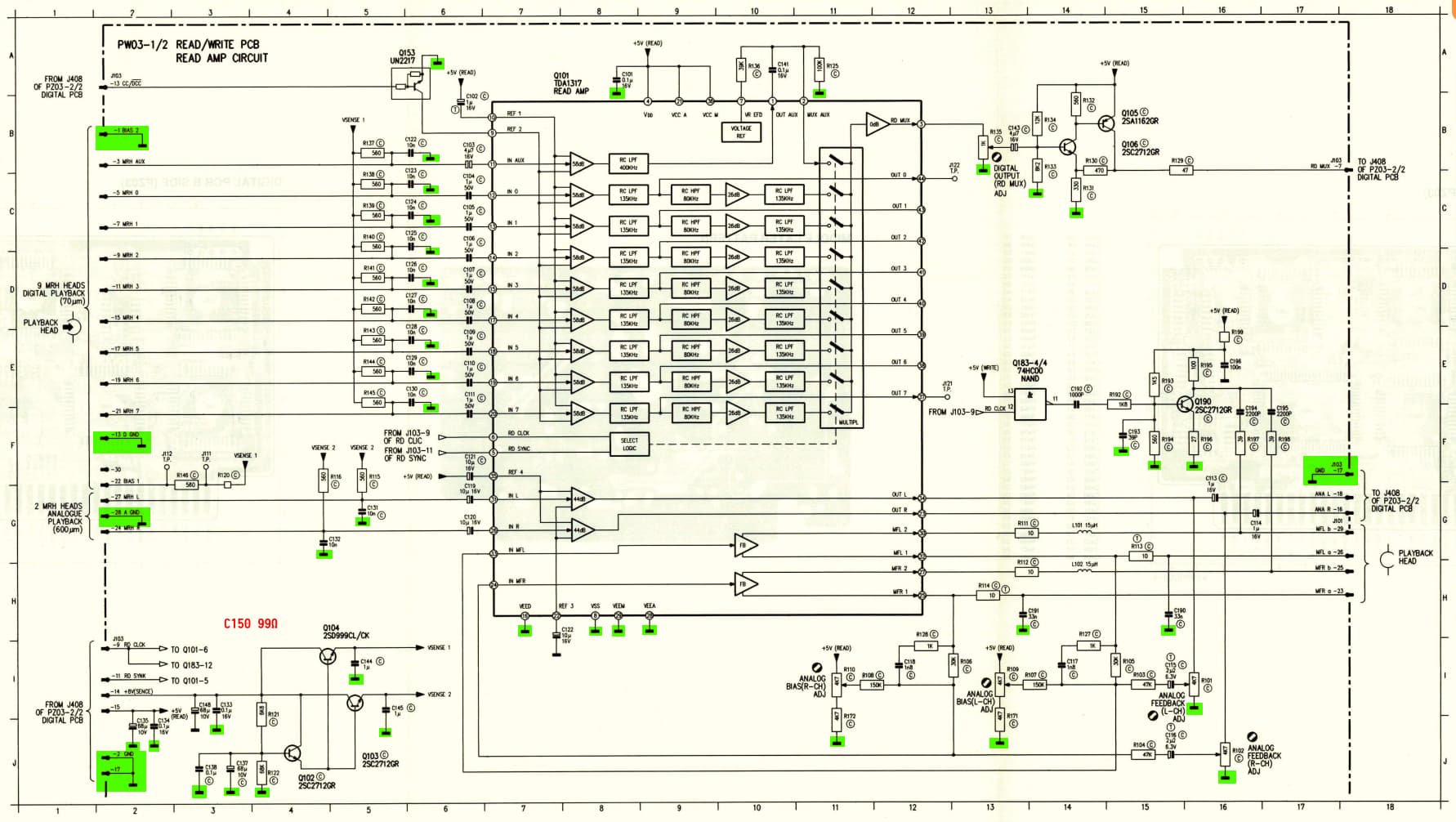
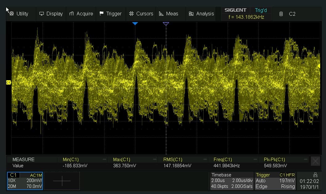
It plays analogue, but there is enormous noise in both channels at -32dB. Measured at the Dolby input (Q601:2 Q601:29) and PW03 output (J611 PG03-5). The noise is there even in stop mode.
Analogue playback has the level ok. THD is low. I’ve adjusted lows and highs to a level and playback speed. Head was cleaned with IPA.
I am wondering what could cause the issue? I will be thankful for any suggestions.
It does not record nor play digital. Tested with NOS Philips DCC cassette. It behaves as if it was recording, but plays nothing. I have no prerecorded tape at hand.
My plan is to first perform adjustments and make analogue playback work (with as short total playback time as possible) and then to fix digital.
Could the S/N ratio be improved by adjusting analogue bias? Could someone tell me if adjusting bias affects S/N?
So far I have refrained from even touching those potentiometers, but maybe they were already adjusted by the one, who tried to fix the DCC before me(?)
Two things I am sure of are:
playback level is fine - within 1dB from the one shown on analogue deck used for recording a tape.
Hi,
From the repair status…. It is a harder approach. Even we do not do it like this at the DCC Museum. The Via’s from side A to B… there is a middle ground layer. If that is damaged, there is no hope for your RW board. It is either that, or the head is damaged.
Usually we test it with a working RW board, but since you do not have that, it might be better to send it in to someone who has/is willing to borrow you one.
I’ve always thought of leakage current between via’s caused by acid and corrosion in the middle layers. You might want to try to interrupt the track and connect the analog signal directly by wire. Never tried it myself though.
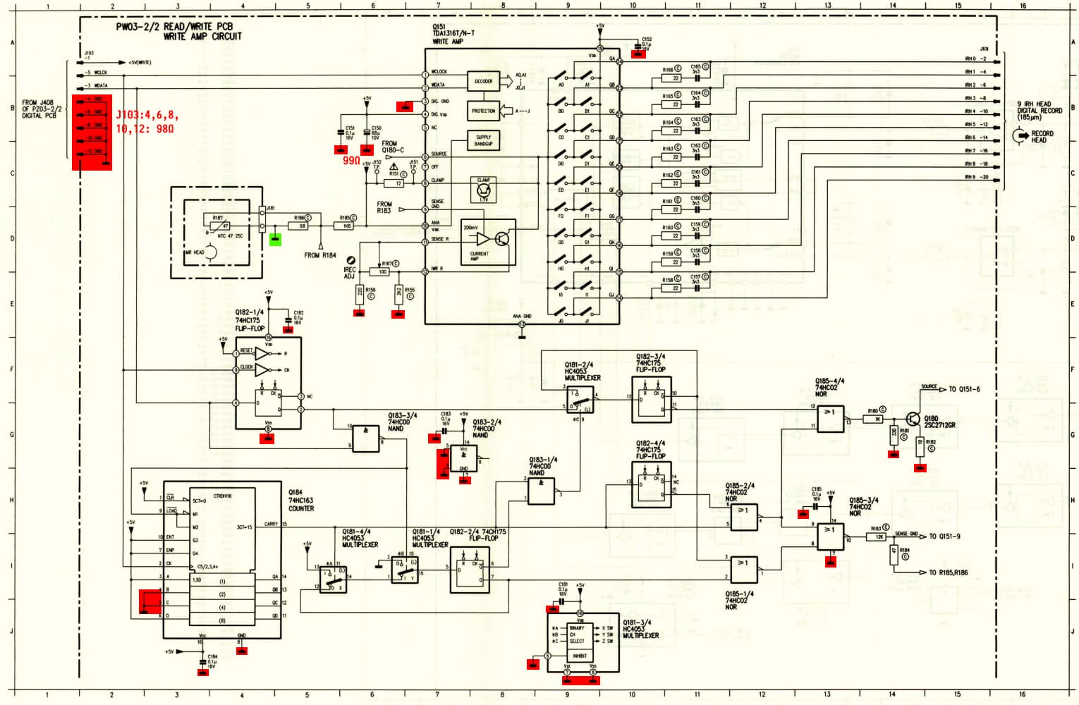
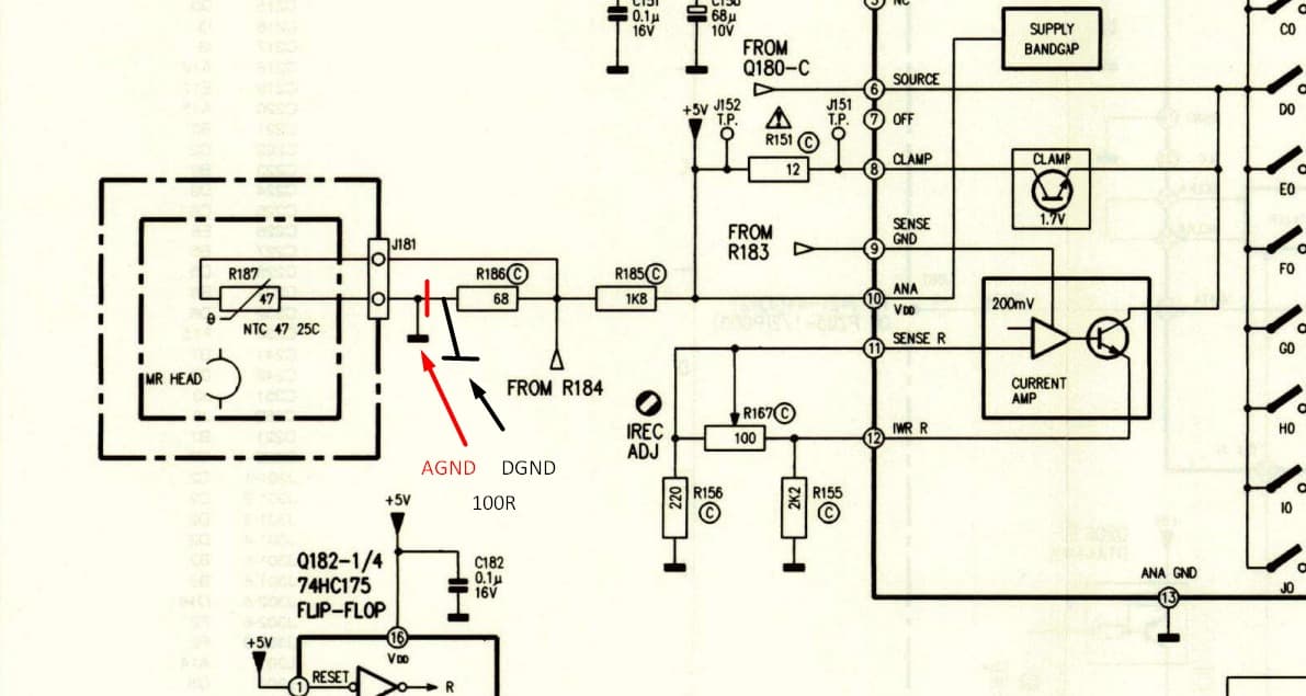
I have measured grounds one by one and noticed there is about 100 ohms between part of them. See schematics attached. It looks as if the 100 ohm is between analogue and digital grounds connection point.
So I soldered two jumpers - J103:2-4 and J103:2-12-17 connecting all grounds at the input. So far didn’t verify all the grounds once again, but it is inevitable taking into consideration, that it didn’t help.
Unfortunately, I have no one, from whom I could borrow working RW board.
So, the plan for now is to check grounds again, then +5V etc. and eventually net-by-net.
I checked net by net all of them. They are fine with one notable exception.
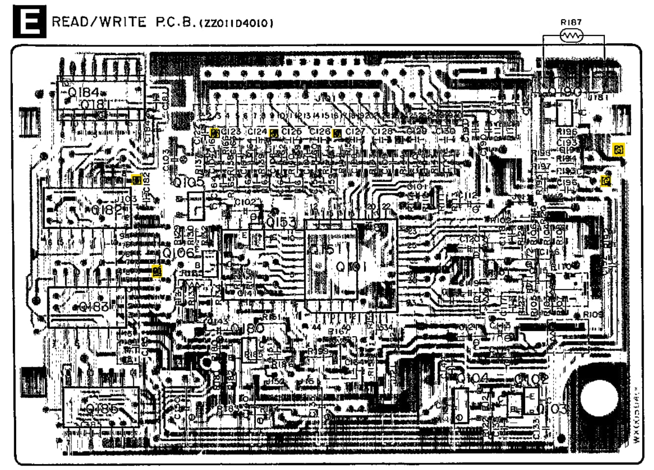
There is no direct connection between R187 (NTC) and R186 to GND. On the schematic, both are connected to the GND. On the PCB one is connected to A-GND and the other to D-GND. Hence, the 100Ω between the grounds.
I’d expect the grounds to be shorted via the TDA1316, but maybe it has failed?
Could you check for me if you have the 100Ω as well?
No progress - still high noise in ACC mode. Digital recording pretends to work, but as playback is silent and no markers are read back quite probably does not work. I have no recorded tape to check.
What have been done:
Tape speed adjustment.
Azimuth adjustment (for ACC).
DDSP IC 24kHz 50% duty for the servo checked.
Analogue playback frequency adjustment (adj. range for highs was bit off needs).
Level meter sensitivity checked.
VCO free run frequency adjusted.
PZ PCB has elcaps replaced with MLCCs. Vias checked.
Wclock and Wdata during recording. Seems fine, but signals are 5Vp-p, whereas service manual states 0.2V/div for all oscillograms. It would mean ~0.5Vp-p. I guess it is a typo. There are a lot of these in the service manual.
Voltages on the Q101 (TDA1317), Q151, Q181, Q190 against values given in the service manual.
Differences: Q151:21 3,55V instead of 0V. Q190 E 0.65V (0V), C 2.5V (3.0V), B 1.35V (1.3V).
Notably, for the IREC ADJ circuit, R156 is 180Ω instead of 220Ω and R155 is 2.2Ω instead of 2.2kΩ as in the service manual. The second difference is huge. Could someone confirm the 2.2Ω?
R183 (to SENSE GND) is 8.2kΩ instead of 12kΩ and R184 is 56Ω instead of 47Ω.
Net by net connections - all fine with an exception to the GND - as I’ve written in my previous post.
UNLOCK signal is 5V even during recording. It may be some hint.
@Henrie The leakage seems to be an option. Maybe I’ll measure via-to-GND resistances. But still, it may be a tough task to identify such a leakage. Nevertheless, worth trying.
A reference, working RW PCB would be tremendous help. Unfortunately, I know no one, who has one. Maybe one of the forum members could offer a helping hand?
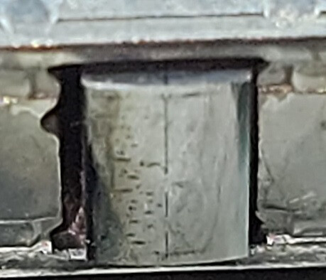
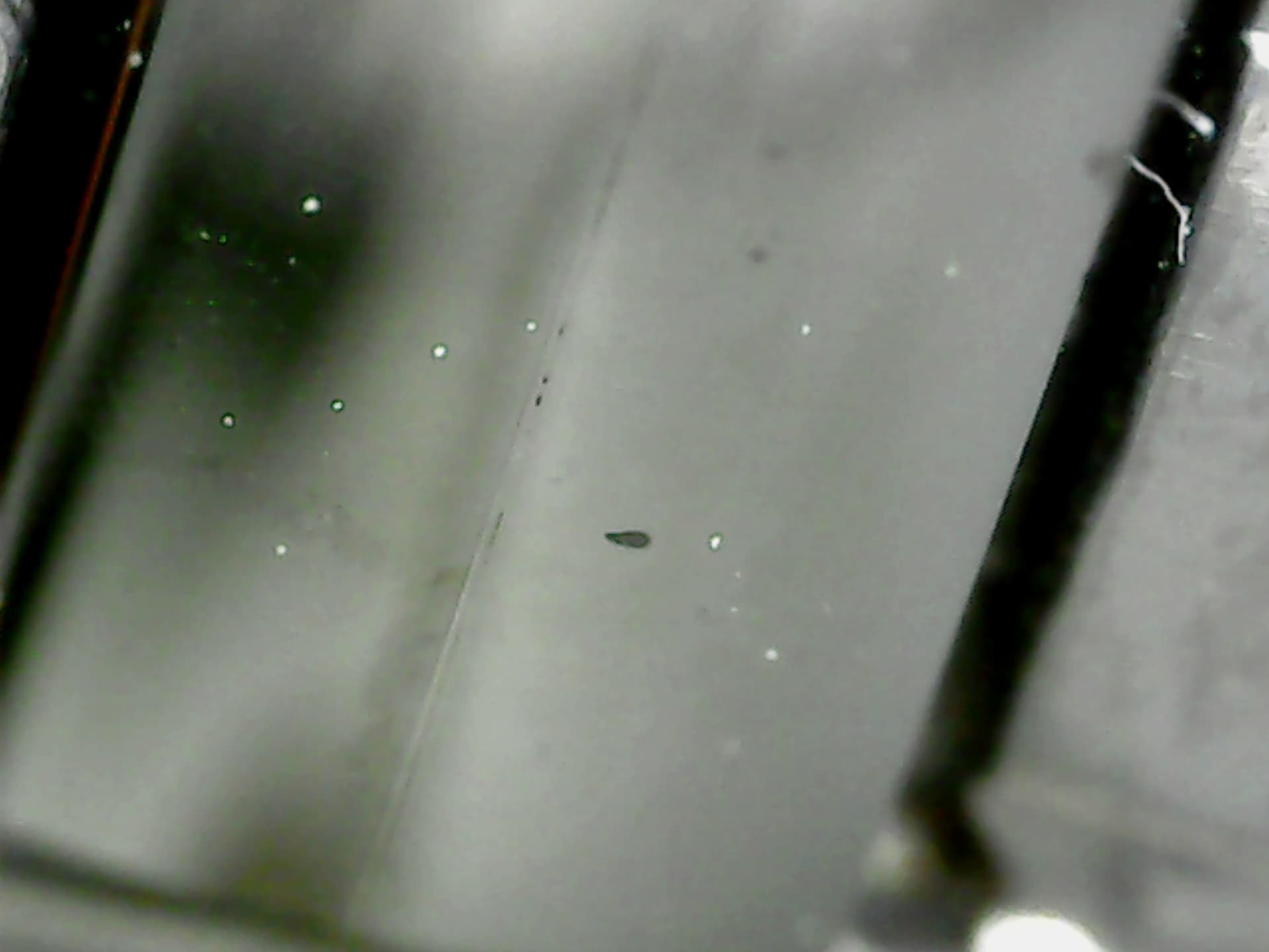
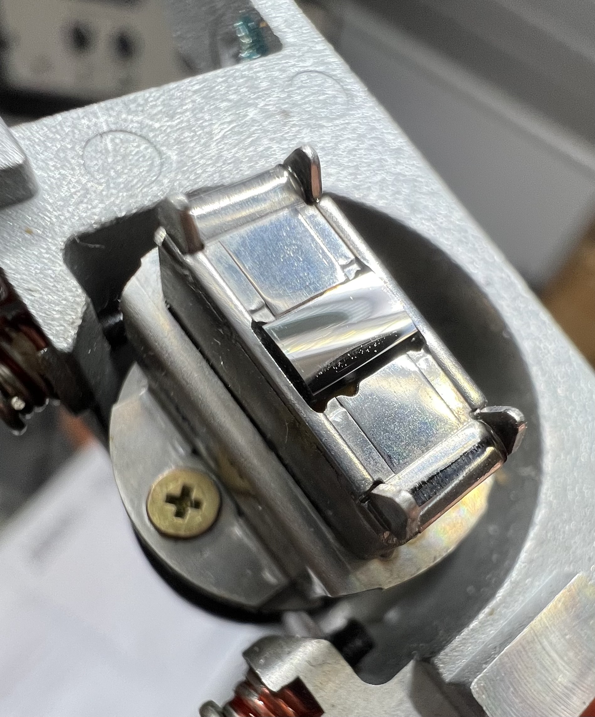
Can anything conclusive be said regarding the head based on the photo?:
https://imgur.com/cxhRNwc
(click on the link to see the photo; the link is ok, just the preview fails)
Technics RS-DC10 service manual has RW board’s layout drawing (page 43), with connections to the middle ground marked with [G]. Unfortunately, none of the two different scans I found online is readable.
Is there somewhere a readable, preferably colour copy? Maybe someone has a printed version and could help?
Regarding the head condition I would bet that it is dead.
Will be good if someone from DCC Museum can take a picture of the new head with the microscope. I am interested as well in that.
I suppose that for the new and good head we should not see the black dotted lines (9 digital and 2 long analog tracks) on the surface.
If the black for tracks is already visible it is either the dirt or starting of corrosion.
This does not influence much the analog part but its fatal for the digit.
I have the DCC900 manual and indeed pictures of the RW board in it are much better, than in the RS-DC10. I know them pretty well. But only the second one has markings showing which grounds from outer layers are connected to the middle ground layer. I mean the [G] marks. That is why I am looking for a high quality scan of the RS-DC10 service manual.
Regarding the head, the photo was taken after cleaning with IPA. Apparently the head is worn, but could one be sure it is dead? The gap seems not to be affected…
Has anyone of you tried A.N.T. Audio head lapping service?
Despite it mentioned (only in Technics SM!) that RW board has 3 layers I do not think that it has those or least it is important to have it otherwise it will be presented in Philips SM like for digital board on page 32.
There is also Marantz DD82/92 manual which does not mention the mid layer for RW board.
Most probably, you’re right - the head is dead. The only thing that gives me a bit of hope is thought, that crucial is the gap condition and not whole its face. Still, looking at the photos you’ve shared shows that, the head is fragile and gets broken easily.
I am wondering if head lapping could help? From what I have learned, it is hard to get a unit with the head in good condition.
As to the grounds - could someone tell me if there is about 100Ω between analogue and digital grounds of the RW board?