DCC850, which IC is this?


Hello, my DCC850 has some issues playing the right channel (among other issues), but i have found out that if i push a bit on this IC with my finger, it will play the right channel but only for a short while.

Nothing to be found visualy although this board was not spared during the testperiod according to the many rework on the board.
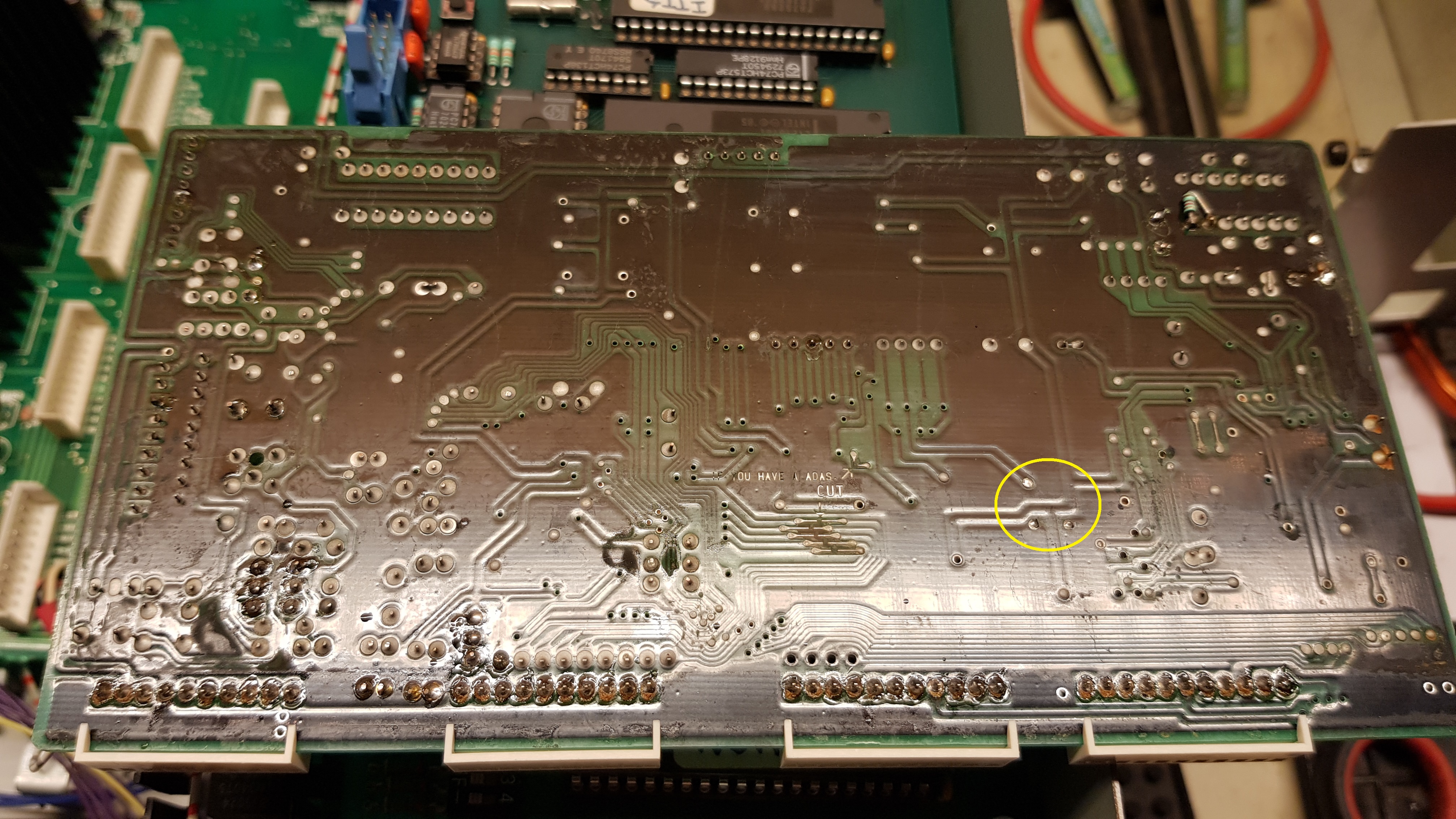
This is the digital board which receives the data from the R/W board.
I can’t find a datasheet, don’t know what this IC will do. There a two of these on the board.

I did some rework on this IC but it didn’t change anything. You would expect a broken trace but nothing is to be found all visible connections are there, at least at the time of checking.

Who knows which IC this is and what is does? the readable text is " ES2 9045 6409 100 "

in Dutch:
Mijn DCC850 heeft wat last met het laten meedoen van het rechter kanaal ( en nog wel meer, maar dat komt later) en inmiddels heb ik na veel proberen uitgevonden dat als ik met een vinger op dit IC druk rechts weer mee wil doen. Dat duurt een tiental seconden en dan is het rechterkanaal weer weg.
Ik kan er echter niks aan ontdekken, behalve dat dit proefdier echt beproeft is geweest want bijna geen IC is er niet eens afgeweest zo te zien.Er is aardig op rondgespit maar niet destructief zoals je ook wel eens ziet.

Het probleem is dat er geen schema is en dit nu net niet lijkt op wat er uiteindelijk in de DCC900 is terecht gekomen.
Het gaat hier om het Digitale bord waar de data van het R/W op het loopwerk op binnenkomt.

Ik kan echter geen datasheet van dit IC vinden, ik weet niet wat het ding doet. Er zitten er twee op het bord.
Nasolderen hielp niet en alle herkenbare verbindingen zijn doorgepiept en ok, altans op het moment dat je het controleert.

Wie weet welk IC dit is? wat erop staat is" ES2 9045 6409 100 "

1 Like

Wow, a DCC850 where you can see the nice cover art of DCC. Honestly, this looks like cold solder joints to me on this one IC, maybe you get contact while probing and thus are unable to measure it. I would suggest trying to resolder that carefully with new solder and then wicking excess with solder wick in case there is any, I am not sure how it looked before.

If pushing on it makes it work, even for a few moments, then that has to be an issue with one or more pins not making contact, or with a cracked circuit-board trace.

There seems to be a lot of crud around the pins on that chip. You may need to get in there with a brush and some flux-removal solvent and give it a good cleaning.

I usually recommend Microcare General Purpose Flux Remover and a good acid brush, but 91% Isopropyl Alcohol will do if the Microcare stuff isn’t available where you live. Either way, just make sure you rinse off and blot up the stuff as it dissolves, or it’ll just redeposit back onto the board when the solvent evaporates.

Once you’ve gotten rid of as much of that brownish-looking crud as you can, reflow all of the pins, preferably with solder that has a no-clean flux, not rosin-core. (Since these boards were made before lead-free solder became the standard, I recommend Chip Quik SMDSW.020, though again, it depends on what’s available in your country if you’re not in the USA.) A flux pen to further scrub and clean the connections before you resolder them might also help.

1 Like

Looking at your board it could be that both are being used for either L/R.
If you agree with that logic and feel confident, you could swap them and see if the problem moves to the other channel? It is trickier to remove though. Then you would isolate the problem as either IC related or connection problem.

1 Like

Also checked if our first dcc900 that came immediately after the 850 (9206 prod date), maybe had this ic to assist.

This is the first time I’m seeing the insides of the DCC850 (I never had a chance to see the inside of the one at the DCC Museum). That board is clearly designed for hardware debugging: all pins are named, there are lots of test points with headers, and it has several patches. Beautiful!

Judging from the location and the fact that there are two of them, the ES2 must be digital oversampling filters. The number is probably a temporary internal designation.

If you push it and it starts working, it’s probably a bad solder connection. However if that is not the case, it’s probably still possible to fix the problem. If anything, it might be possible to wire a filter chip from a first or second generation DCC recorder in its place.

The M51581 is the Digital Audio Interface (DAI) which handles the SPDIF inputs and outputs. It’s also used in other DCC recorders. A datasheet can be found online.

SAA2011 is the Adaptive Allocator and Scaler which is used for PASC compression during recording. There is no datasheet but it’s used in other DCC recorders too.

(N)SAA2030 is not used in any other DCC recorder but other recorders use the SAA2031 for Error Correction (ERCO) so I bet the SAA2030 is an earlier version of that.

SAA2041 is used in other recorders, it’s the Digital Drive Signal Processor (DDSP) which controls the capstan motor speed and some other things (possibly tape formatting, since it’s connected to the M41464 which is a RAM chip). There is no datasheet as far as I know.

ADC017 must be the subband filter (SBF), judging from the two crystals right next to it. It digitally divides the PCM signal into 32 frequency bands during recording, and vice versa during playback. It also provides timing signals, hence the two crystals: one for 32 and 48 kHz, and one for 44.1 kHz. It’s not used in any production DCC recorders (unless maybe the same chip was renamed later) but I think the prototype portable recorder at the DCC Museum may have one of them too.

AD023 must be the Digital Equalizer (DEQ) which reads the analog signals from the Read Amplifier (which is on the analog PCB) and digitizes them. It’s not used in any production recorders.

This information is based on datasheets and service manuals that can be downloaded from my website digitalcompactcassette.github.io

=== Jac

Thanks for all the tips and advice! It is working again :smiley:

On MFBfreaks.com was suggested by Bram that these IC’s could be the SAA2001 and Mae suggested like Jac that it could be an early version with an intern number and the ‘9045’ on the chip could be a date code.


So here’s the board on top of a part of the DCC900 doc with the SAA2001, it turns out that the unknown IC is identical to this layout, everything matches including the signal names.


here is a better view on the board.

So where was the culprit?


On the back in the yellow circle are three points that are located under the IC and unknown is where it leads to. I have resoldered these points and now it plays on both channels.
I can’t figure out why, i was really carefull not to push on the leads when checking for continuity and there were no failures so what would the resoldering of the back add? but obviously it did add something.

short clip (poor quality, sorry)
http://nr3032.nl/diversen/20210110_182308.mp4
now there is more to be done, it is very itchy for the right headposition and side A plays more consistend than side B. I did change the pinchroller for side B before (100% identical to DCC900), this one had a dent in it, i suspect it was left for dead in play position. This helped a lot already but i’m not there yet.

but so far so good!

1 Like

Well, that didn’t take long. Just turned it on again and only left would play. Touch of the magic finger did the rest. hmm

1 Like