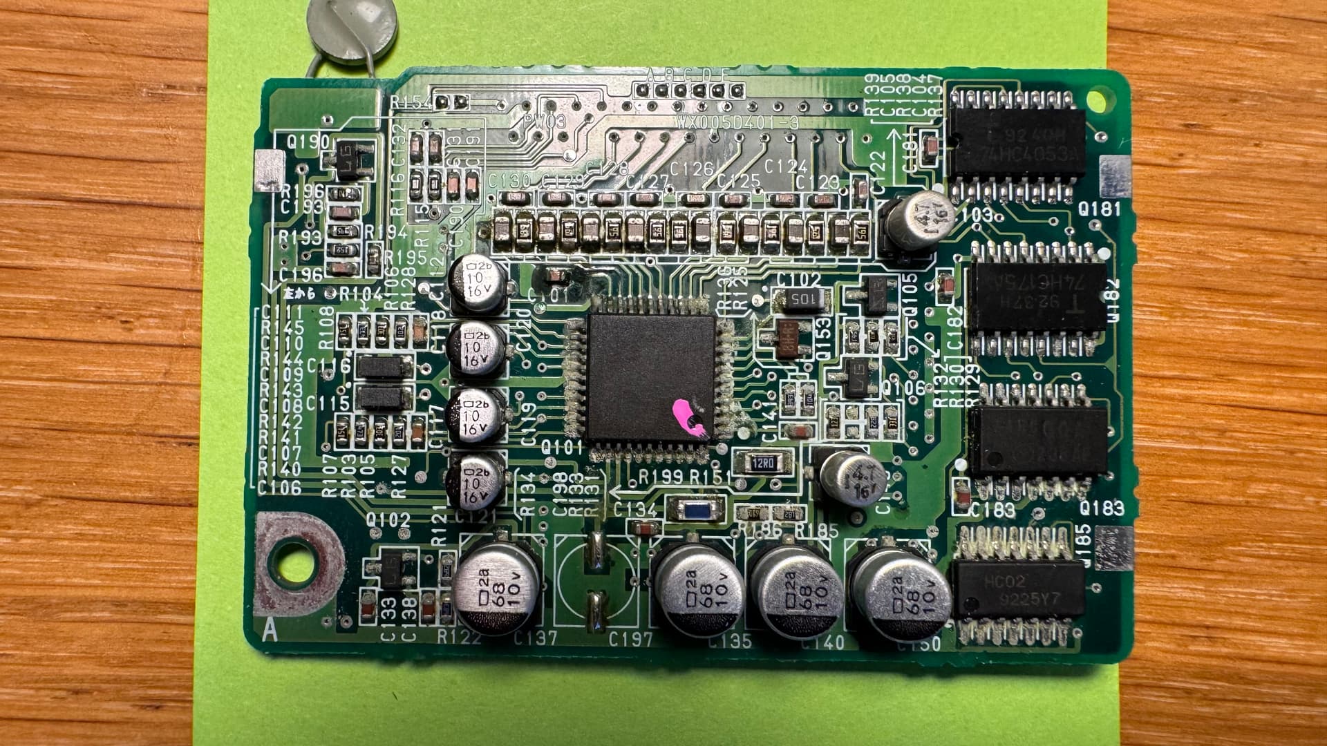
I’m restoring my original Philips DCC-900 and luckily it’s in very good shape. Everything appears fully functional, but I’m mindful of the warnings to replace the SMD capacitors on the two boards that have them. They look pristine to me but I imagine they should they be replaced anyway - does that sound sensible?
By my reckoning there are 4x68𝛍F, 9x10𝛍F, 2x4.7𝛍F and 2x22𝛍F to replace, does that match what other readers have found? I’m only missing the 4x68𝛍F so if I’m right that’s not too bad.
First generation DCC Players, like the Philips 900, Marantz DD82 and DD92 the Optimus DCT2000 and Technics RS-DC10 all need to have their smd capacitors replaced. In this video we will show you we do this at the museum.
That’s priceless information, thanks @drdcc Can’t believe I missed the ‘.’ in that 2.2𝛍F.
Pardon my ignorance, but is there a practical reason to replace the SMD caps with non-SMD caps? Checking at Mouser, for example, most of the Nichicon caps mentioned are end-of-life/un-stocked, but I can get hold of SMDs with the same characteristics quite easily.
Thanks once again! For my sins I’ve repaired way too many motherboards so I have the kit to make SMD replacement not too onerous. I’ll let you know how I get on once I’ve received the caps and re-done the boards
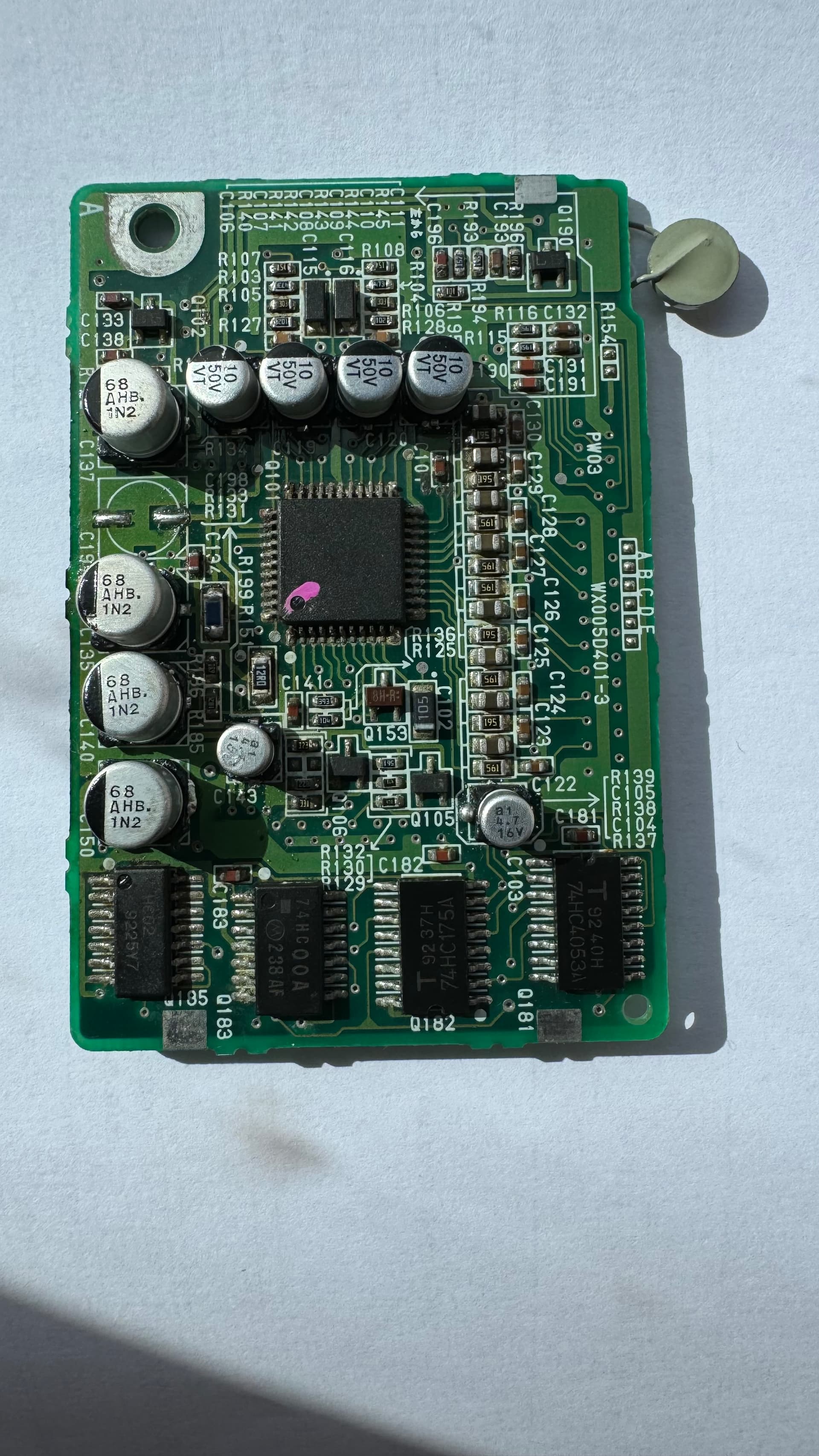
Here I am again So, the replacement capacitors have arrived, I’ve removed the originals and acetone-cleaned both boards. There was some damage but I’m pretty lucky, the machine was still working, the boards now look in pretty good condition.
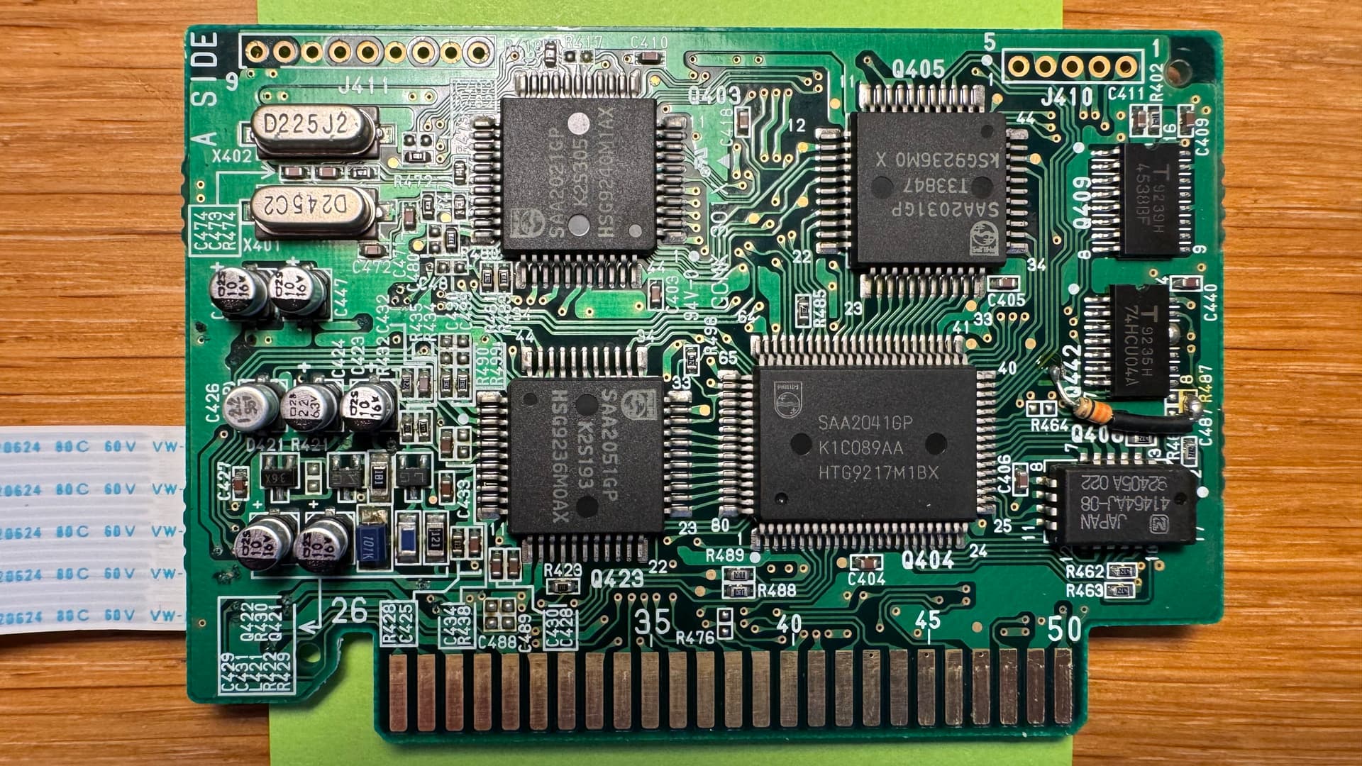
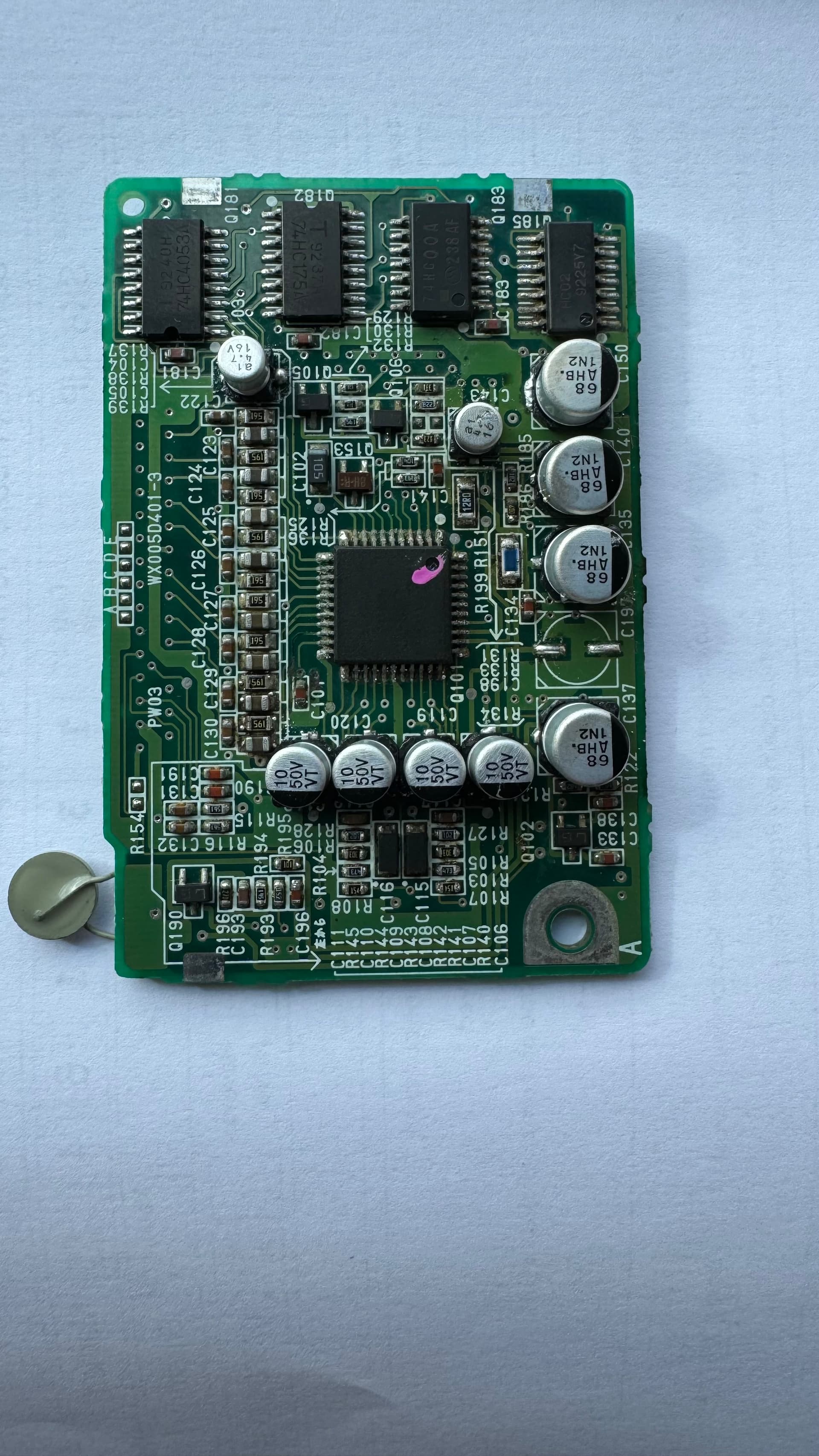
My next step (following the superb cap replacement video from DCC Museum) is to run the boards through an ultrasonic cleaner, but I noticed there are a couple of oscillators on A SIDE of PZ03 (X401 and X402).
I’m wary of putting an oscillator in an ultrasonic bath, but X401 and X402 are 24.5MHz and 22.5MHz respectively, and the bath is 42KHz, so it shouldn’t pose a risk, should it?
OK, time for the next phase. After (finally) getting the components and tools I needed I’ve completed the capacitor replacement, everything seems OK on the two boards, but when I power up the DCC 900 the display is blank, and no response from any controls. When I power it off there’s a release sound from the deck mechanism so power is getting through, if I were to guess what’s up I’d say the flat connector between the two boards. I cleaned the contacts but they don’t look in good condition at all.
Might that fit with any evidence you’ve seen in the past? I’m going to start the hunt for a replacement cable
So, the FFC ribbon between the two boards has been replaced and the DCC 900 has come back to life, display and controls working fine. Playing a DCC, though, there are no dB readings on the display and no sound. (Although it displays READING and the 44KHz symbol is lit.) So I’m guessing either (1) my cap replacements were bad, (2) I’ve fried the board somehow, or (3) the flat cable connecting the board to the head isn’t connected properly.
Might anyone have any troubleshooting/diagnostic steps I can follow to help narrow down the problem? I’d prefer not to have to disconnect the head board again, that plastic ribbon looks very fragile.
Could still be the read-write board or the head.
To test the head, you can download the service manual to see what the status is (pressing play+power and then power on, will get you in the service menu).
Thanks once again @drdcc I’ve not found any definitive information on the status mode (play+stop then power on in case anyone’s following along), but the ALL ERR DISP constantly flickers between 10 11111111 and 11 11111111 and the ALL ERR RATE is FD FFFFFFFF.
Might that narrow down the cause of the problem? I’m also wondering if I could make an ‘extension’ for the head/board connector, the 30-pin one, to protect it…
That indicates that the head is completely dead. F and 1 means, dead channels.
Theoretically it could also mean a problem on the read-write board, but in my opinion it is, most likely, the head.
Ouch, but thank you. I had my ESD protection connected all the time, but I understand that the heads are very sensitive. If it is the head, then I’ve fried it while removing/replacing the read-write board, which is really sad. It played fine before I started replacing the caps. Or … might I get the same status mode readings if the 30-pin head/read-write board cable was not connected properly or faulty/broken in places?
Actually that is another possibility. If the connection between the head and read-write board is not correct, you could see these readings as well. Double check that connector again.
So, I went back to basics and decided to start with no digital board, then connect each board and cable, one at a time, (powered off of course!) and run the service tests after each connection:
With no digital board (PZ03): 11 11111111
With PZ03 in place: 10 11111111 and 11 11111111 flickering
With PZ03 18-pin cable connected at one end: 10 11111111 and 11 11111111 flickering
With PZ03 18-pin connected to the read/write board (PW03): nothing. No display, no controls working, just the sound of relays switching when the power is switched on and off.
So I’m at a loss once again — when PW03 is connected, the whole unit is unresponsive. Might that match any experience you’ve had before? Continuity meter confirms pins 1-18 are connected between PZ03 board to PW03 board. The behaviour is the same whether the head is connected or not.
It would be hard to determine exactly what is wrong now, without having it on our bench.
Happy to help. You could send in the mechanism and both boards for repair/review.
That’s extremely helpful, thank you! I’m disappointed that I couldn’t work it out myself but would be very happy if you could check it out for me. If you could let me know the process (Patreon membership, costs involved etc.) I can start preparing the parts for shipping