HI
I have just recapped the two small PCB of my second hand DCC 900, I got lots of drop outs before, now it reads DCC cassettes perfectly, only a prerecorded cassette has a lot of drops out during a song (I suppose it’s a tape problem).
Analogue cassette ik OK too, but left channel is lower than the right. not that important before I do not read analogue on this DCC.
so what I have on “all data rate error” is 0000000F
what does "F mean ?
thanks a lot.
(I read that I can receive belts and pinchrollers for this DCC 900 via a patreon DCC Museum ?)
DCC can still decode the data with 1 non-working track. But it can happen that periodically some other channels will have failures (also due to the condition of the tape itself) and then you will have a drop out. That is probably happening on you prerecorded tapes already.
When the next track on the head of DCC900 will get a constant F it will be the “end of the game”…
It is not recommended to use the ACCs - the old tapes, specially type 1, can harm that DCC head. But in case of you still would like to improve the analog part it is possible to tune it with R109/R110 and R101/102 on the RW board.
Do you have the same F on #8 on the B-side of the tape?
thanks for your support. I will check side B and other tapes. So you mean it is not a dcc 900 hardware problem, but rather a tape problem on this cassette and maybe other ones too ?
This is the HW problem (highly likely) - all the tracks must show 0 or periodically can show 1 across all 8 tracks during the playback, if some errors from the tape occurs.
You can record something on the tape (better a blank one) and see if you still have the F for track 8 during the payback in the service mode. If it is so it means that the head is dying slowly.
If all tracks will like 00 00000000 then you are lucky, and the head is OK and you probably just need to try to rerecord the tapes.
first 00 digits are for AUX ch (text messages, markers and etc) they are not that so much important. But the next 8 digits are vital.
I have the DCC900 which has 0F00F000 and it produces only some peaks of the sound - can’t decode the PASC in full.
So you are still lucky that your unit has only a single track failure. As mentioned earlier once the second track on the head will die it will stop playing.
So to extend the lifetime of the head I suggest not to play ACCs at all on this deck and quite often to clean the head with alcohol.
By the way did you try to clean the head? Maybe you just have some strong dirt on the head for track #8?
well, when I recapped I cleaned indeed the head, with isopropylic alcohol and cotton swab. do not know if I cleaned it enough, not so easy to do with the 4 guides on the corners. so technically, with this one track failure, does it mean that the head can not render perfectly all frequencies ? or that something is missing in the sound ? beacause so far, I barely can’t hear the difference with a cd.
my question is perhaps stupid (sorry) : when reading an analogue cassette on service mode, I have 00 00000000 this time.
is it normal ?
well it is PASC algorithm very similar to MP1 which was (and probably still) very good even has 1 to 4 compression rate.
So the music is coded across all 8 tracks and the system can still decode it back in full without the major loss from 7 tracks.
So maybe you can try to clean the head once more. If you have magnifier you can also try to look at the head and see its condition.
Track#8 it is the last one in the column, and it is close to the mid of the head.
I cleaned again the head. it seems really like brand new. They certainly did not play many cassettes in there.I can not see any scratches. I have no magnifier, though. anyway, same F error. again. I wonder if the thin cable running from the head could be the key of the error : when cleaning the head I saw that the metal connections on the pcb of this cable seem a bit “rusty” from the acid vapors of the bad capacitors. perhaps I will try to disconnect it again and clean with deoxit.
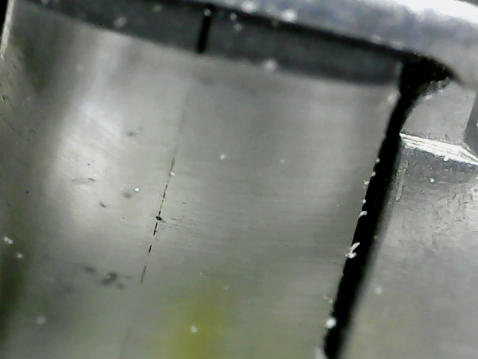
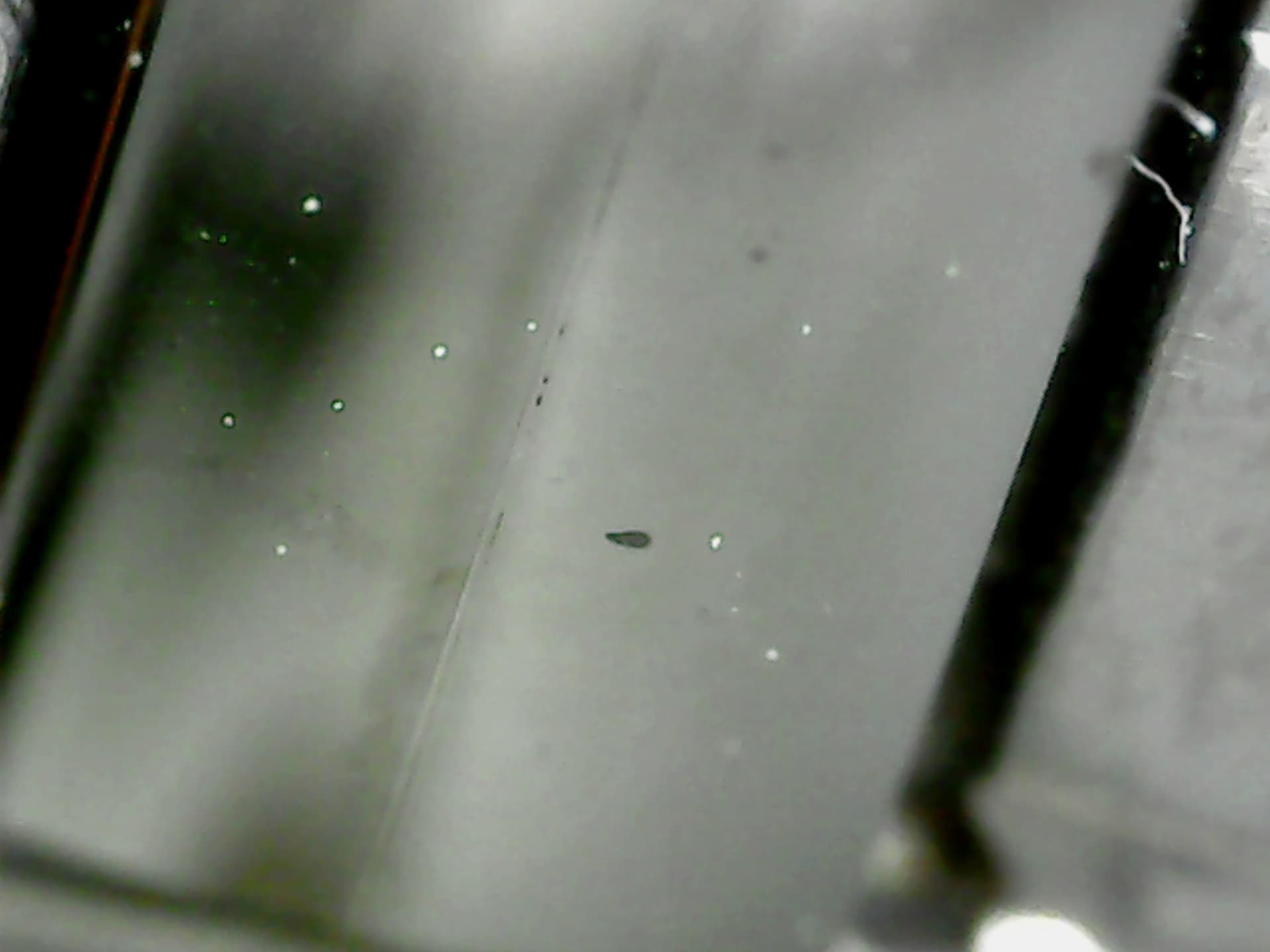
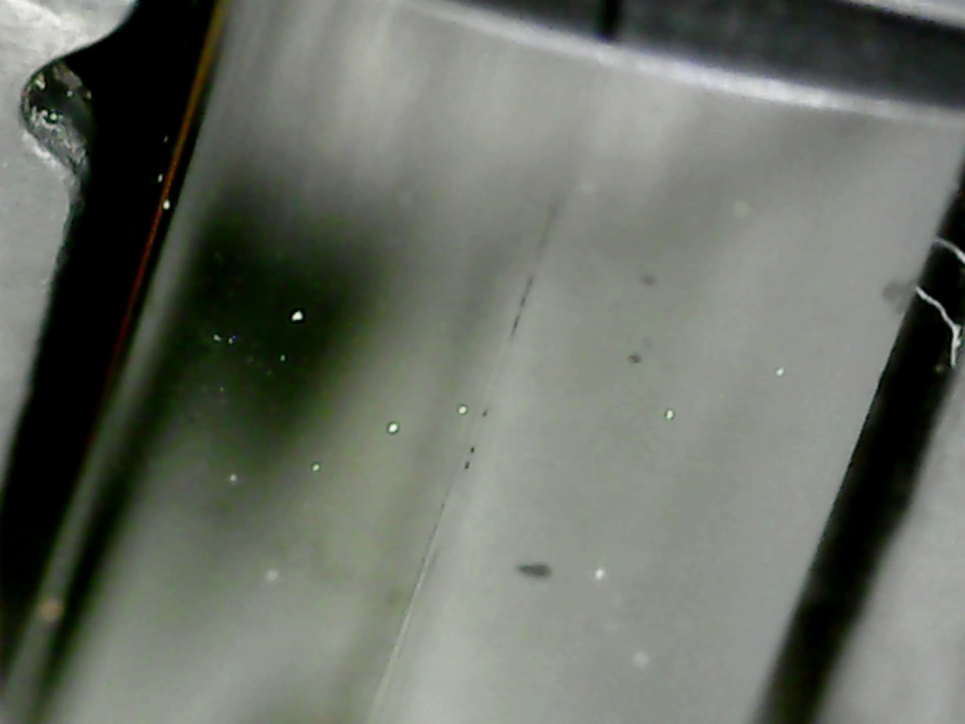
It only seems. Pity that for unknown reason I can’t load here for you a picture of the head with the high zoom… I am getting the message when I am trying to attach the picture - Unsupported header ‘x-amz-checksum-crc32’ received for this API call
Well the cable can be a case as well but not necessarily. On some DCC900 I have to restore this cable, but there was evidence that some tracks were broken on the edge of the cable connector. I was measuring each track to the pin13 (GND) and thus discovered that ie some recording wires were faulty. But that worked only for the one head out of 2..3!!! and only because the head itself was good. And you should be really careful dealing with this cable.
So if you magnify the head, you will definitely see the defects even now it looks very much polished.
thanks fir your advice. I just bought another dcc 900 on ebay, 170 euros, sold as “defect”, mechanism OK but no output and nothing on the screen. perhaps the head is ok and will see after recapping the 2 pcb. it could be anyway a donor head, will see… hopefully you can post this picture of this head, perhaps there are holes on mine indeed in the area of track 8.
you can also try to use the whole tape drive mechanics of the new unit with your old RW and Digital board and see if the head is ok or not. your old boards are ok and you know that they are working. You will get the result faster.
It is better do not disassemble the head in order not to deal with the azimuth setup latter if you do not have a mirror tape!
By the way I had 1x DCC900 that was not working, I was thinking that the problem was with the boards. I brought another 3!! units from Japan (2x DCC900 and 1xRS-DC10). And only one head was alive out of 4 units at the end! The boards even they can look very damaged can be 99% restored but once the head is dead it is ~FF FFFFFFFF in some combinations.
So I decided not to deal anymore with it It is a big lottery.
And if the head is so tender and can be damaged by use of the normal tapes its crazy - it kills the whole idea of DCC.
I suppose I can check continuity of the track 8 along the ribbon ? maybe it’s just a broken link somewhere on the edge of this ribbon, I’ll check the metal edge of the connector of this ribbon to the read/write pcb. I can also put one probe gently on the head in the track 8 area, and the other probe on the opposite end of the ribbon ? Or there’s no continuity when system is OFF and this check is not possible ?
yes I ll do it with the new unit (with my old working 2 pcb)
I have a mirror tape if I transplant the head, I can check azimut. hopefully there is no tilt and height setting on the head ?
the wires “normally” can break only at the place where the ribbon cable changing its state from flexible and covered to the firm (area that opens the wires for cooper pins).
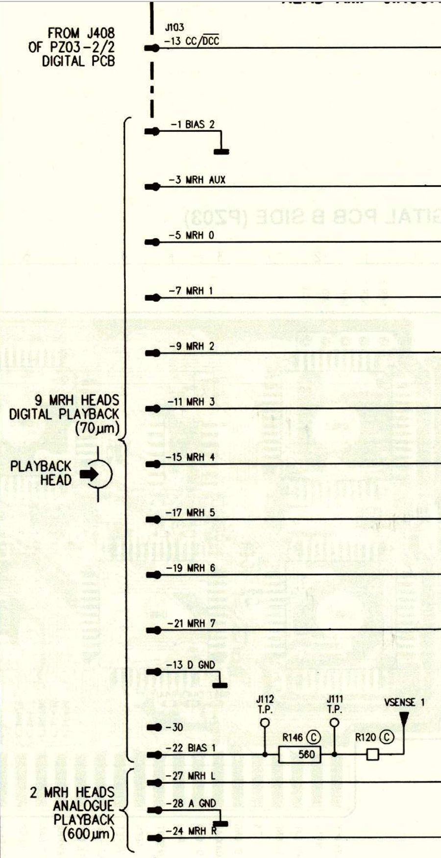
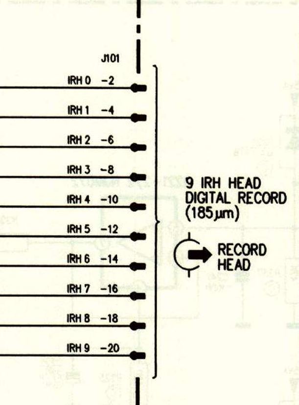
you should check the connection with the ground pin 13 for each even numbers from 2 to 20 for recording heads and odd numbers from 3 to 21 for playback heads.
Of course this can be done when the tray with the head is out of the unit and has no connection to the boards.
thanks Sergey, I’ll do it. I suspected there could be a broken link on the ribbon to the head, but it’s very unlikely, because of the screw that maintains the ribbon close to the head.
Ok, what do I have to check : continuity ? between pin 1 to 21 and pin 13 ? because there are only a few pins (2 or 3) that have continuity with pin 13.